Canada’s Instrumentation Leader Since 1946.

Canada’s Instrumentation Leader Since 1946.

 Hoskin Environmental
Sampling and monitoring instruments for air, water, weather and soil for the environmental, agricultural, mining and research markets.

 Hoskin Geotechnical
Materials and Product testing for soil, asphalt, petroleum, concrete, mining, cement, and research industries.

 Hoskin Instrumentation
Sensors, transducers and instrumentation for industry, manufacturing, research and development and factory automation.
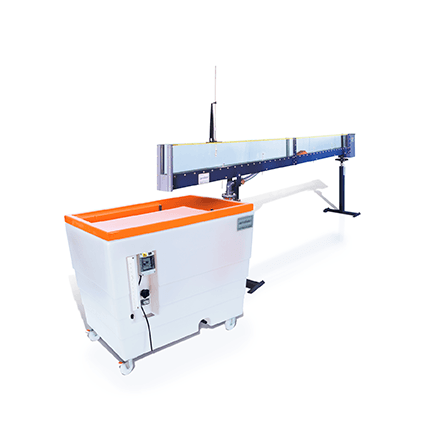
DESCRIPTION The Armfield Multi-purpose Teaching Flume has been specifically designed to demonstrate the principles of fluid mechanics when applied to engineering structures in open channel flow. The C4MKII is a small open channel flume, available in 2.5m or 5.0m lengths, with clear acrylic sides to the working section for complete visibility of the flow. The […]
 Contact us for details
DESCRIPTION
The Armfield Multi-purpose Teaching Flume has been specifically designed to demonstrate the principles of fluid mechanics when applied to engineering structures in open channel flow.
The C4MKII is a small open channel flume, available in 2.5m or 5.0m lengths, with clear acrylic sides to the working section for complete visibility of the flow.
The channel is fitted with a PVC inlet tank, and is designed for free discharge into the Hydraulics Bench. The flume is mounted on a rigid framework, and can be tilted by use of a calibrated screwjack, which enables accurate slope adjustment of the channel.
The inlet tank incorporates a stilling arrangement to diffuse the water flow prior to entry into the channel, ensuring smooth uniform flow. The level in the working section of the flume is controlled using an overshot weir (stop logs) at the discharge end.
Bed-pressure tappings and fixing points for models are provided.
A longitudinal scale positioned at the top of the channel enables depth gauges and pitot static tubes to be accurately positioned along the channel length.
The flume is designed for use with a standard Armfield F1-10 Hydraulics Bench, which provides the pumped water flow, the flow control valve and a volumetric tank for flow measurement.
Also available is an optional flow meter, which can be fitted to the C4-MKII to enable direct flow measurements to be taken.
Optional educational software is available (C4-MKII-ABASIC) offering a complete teaching package of coursework. The student manually enters data in the software, which can then be used for calculations, data processing and graph plotting.
Requires Hydraulics Bench Service unit F1-10
DETAILED EXPERIMENTAL CONTENT
ACCESSORIES SUPPLIED WITH THE STANDARD FLUME


Experimental Content


Copyright - 2026 - Hoskin Scientific

